Portal Rendering with Offscreen Render Targets
This entry was originally posted here back in 2015. I’ve ported it to Markdown to help get me started on this new blog.
The old blog will likely be retired sometime in the future…
This is an attempt at explaining how to implement portals using an offscreen render target. It’s a technique I didn’t know a great deal about up until quite recently and after messing around with it for a while I thought it would be cool to describe the approach. Hopefully, people might find it interesting.
The problem consists of three main parts.
- Transform the portal camera relative to the portal destination, based on the translation and orientation of the main camera relative to the portal source.
- Render the scene from the perspective of the portal camera to an offscreen render target.
- Apply a portion of that texture to geometry viewed from the main camera with the correct projection.
I will visit each point in turn over the course of this post and try and explain each one thoroughly.
I’m using Unity as it cuts out a lot of the nitty gritty that you might have to deal with getting setup with OpenGL or DirectX. The principles will all hold true no matter what library/engine you’re using and porting these ideas to other APIs/platforms shouldn’t be too difficult.
The source (Unity project) is available on GitHub here. You’re free to do with it what you’d like. Hopefully, this post along with the code should give you a good understanding of what’s going on. There are two scenes included, Main and Simple. Simple contains just one portal and makes it a little easier to see what’s going on, Main contains two portals and is (slightly) more interesting.

The main Unity scene with some portals
Part 1: Transform the portal camera relative to the portal destination, based on the translation and orientation of the main camera relative to the portal source.
In the scene named Simple, there are two transforms of note, Source and Destination. The source transform is the centre of the portal and represents the position/orientation the main camera will be treated relative to. The destination transform (represented by the red cube) is the transform the portal camera is treated relative to. (Note: I make use of the layers and culling masks in Unity to ensure the red cube doesn’t show up when rendering from the portal camera)
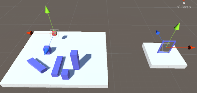
Source (right) and Destination (left) transforms
What we’re trying to do is ensure the portal camera mimics the movement of the main camera exactly, only relative to the destination transform instead of the source transform. If we look at the local position and orientation of the main camera relative to the source transform, and the local position and orientation of the portal camera relative to the destination transform, they would be exactly the same. Basically, if the main camera is 5 units behind, and 10 units left of the source transform, then the portal camera will be 5 units behind, and 10 units left of the destination transform. Below is an example in 2D.
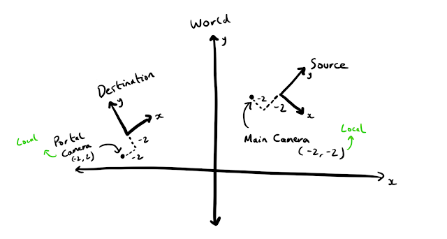
To ensure the portal camera mimics the movement of the main camera relative to the destination transform, we multiply the world transform of the main camera by the inverse of the source transform to get the camera transform in the source transform’s local space. We then multiply that transform by the destination transform to put the camera back into world space. This combines the local transform with the world space transform to give us our final position - the position/orientation of the portal camera.
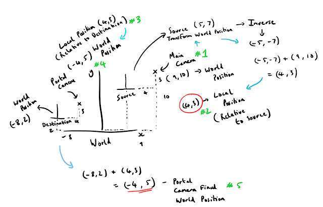
Above are some scribbled notes to try and make some more sense of this (apologies if my handwriting is incomprehensible). The diagram is simplified to be in 2D and we are only caring about position. At #1, we have the main camera position in world space (9, 10) and the source transform at (5, 7). To get the position of the camera in the local space of the source transform, we add the inverse of the source transform (it negated) to the world position of the camera (-5, -7) + (9, 10). This gives us the local transform of (4, 3) at #2. Once we have that, we just add it to the world position of the destination transform #3 #4 (-8, 2) + (4, 3), and we have the final world position of the portal camera (-4, 5)! (Repeated at #5) This is all the matrix multiplications are really doing, they handily also manage rotations but the principle is exactly the same.
This is achieved in Unity with the following code:
public Camera Camera;
public Camera PortalCamera;
public Transform Source;
public Transform Destination;

Vector3 cameraPositionInSourceSpace =
    Source.InverseTransformPoint(MainCamera.transform.position);
Quaternion cameraRotationInSourceSpace =
    Quaternion.Inverse(Source.rotation) * MainCamera.transform.rotation;

PortalCamera.transform.position =
    Destination.TransformPoint(cameraPositionInSourceSpace);
PortalCamera.transform.rotation =
    Destination.rotation * cameraRotationInSourceSpace;
(Note: In other math libraries (glm/DirectXMath) you can likely just multiply the matrices but Unity prefers using position and rotation (exposed as Vector3 and Quaternion) directly from scripts so you have to do each individually.)
It is also important to ensure the portal camera has the same field of view (FOV) and aspect ratio as the main camera to ensure the images match up correctly when doing the projection later.
Part 2: Render the scene from the perspective of the portal camera to an offscreen render target.
Thanks to Unity this step is made very easy. You can see how it is setup in the example project, but basically, all you need to do is create a new asset of type RenderTexture, and then assign that to the Target Texture public property of the portal camera. This will cause the camera to render its view to that texture, which you can then use with a material in your scene.
Part 3: Apply a portion of that texture to geometry viewed from the main camera with the correct projection.
This last part is probably the most difficult and requires you to have an understanding of projection transformations to appreciate what is going on. I’ll do my best at giving an overview and link to some articles/references that do a better job of explaining it than me.
First off, let’s view the scene from the perspective of the portal camera (see below). This is the image that is being rendered to our texture
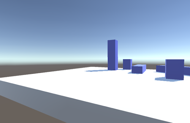
Scene rendered from portal camera perspective that ends up in our texture
If we now look at what we’d like to see from the main cameras perspective, this is what we’d expect (see below). (In the sample project linked at the top of this article you can toggle between these two cameras to observe this effect by hitting ‘C’.)

Scene rendered from main camera perspective
If we ignore all the other geometry, what we actually want to do is map a portion of the texture (the first image from this section) to the red quad below.
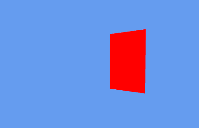
Only rendering the geometry we want the texture to be applied to from the main cameras perspective
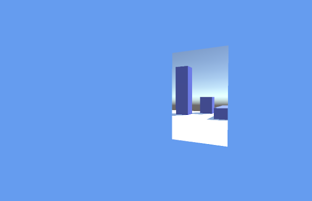
Geometry with the correct portion of the texture applied from the main cameras perspective
If you’re reading this hopefully you’re familiar with taking an object in world space and transforming it to screen space (if not then check out the links at the bottom of this post). The quad we would like to apply our texture to gets transformed from world space to screen space as normal, the trick comes with how we calculate the texture coordinates for it to display the right portion of our texture.
Usually, models have texture coordinates authored for them (ranging from 0 - 1 in X and Y). If we used this approach with the quad in the above screenshot, we would see our texture, but it would be all squashed to fit on the quad and would look totally wrong (see below)
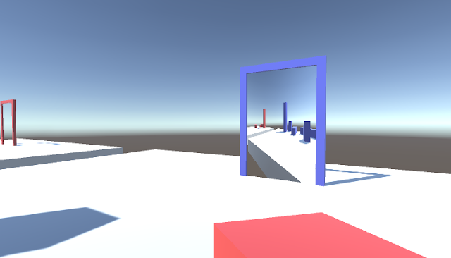
Squashed texture not mapped with the correct projection
Essentially what you want to do is copy a part of the texture into the other scene. The trick is to calculate the texture coordinates for the portal based on the current projection. To achieve this you need to write some custom shader code which I’ll try and explain now.
// Values passed from Vertex to Pixel Shader
struct v2f {
    float4 pos : SV_POSITION;
    float4 pos_frag : TEXCOORD0;
};

// Vertex Shader
v2f vert(appdata_base v) {
    v2f o;
    float4 clipSpacePosition = mul(UNITY_MATRIX_MVP, v.vertex);
    o.pos = clipSpacePosition;
    // Copy of clip space position for fragment shader
    o.pos_frag = clipSpacePosition;
    return o;
}

// Pixel Shader
half4 frag(v2f i) : SV_Target {
    // Perspective divide (Translate to NDC - (-1, 1))
    float2 uv = i.pos_frag.xy / i.pos_frag.w;
    // Map -1, 1 range to 0, 1 tex coord range
    uv = (uv + float2(1.0)) * 0.5;
    // Handle OpenGL/DirectX differences
    if (_ProjectionParams.x < 0.0)
    {
        uv.y = 1.0 - uv.y;
    }
    return tex2D(_MainTex, uv);
}
First, we define a struct to write to the SV_POSITION semantic (this is to provide the vertex position in clip space to the next stage of the graphics pipeline) and also to pass values from the vertex shader to the pixel shader. In this case, we want the vertex position in clip space in the pixel shader, but unfortunately, you cannot access a variable with the semantic SV_POSITION from the pixel shader, so in this case, we create a copy - pos_frag. The TEXCOORD0 semantic is not required on all platforms (though sometimes is necessary) and has nothing to do with the actual value we’re passing (in this case the position of the vertex in clip space - it doesn’t matter it’s not actually a texture coordinate). Using the semantic will however guarantee the pixel shader can access it.
The pixel shader accesses the xy position of the vertex in clip space (clip space refers to the space a vertex is in after being multiplied by the projection matrix. x, y and z coords are in the range: -w <= xyz <= w at this point - see links below for more info) and then does the perspective divide by dividing by the w component. This takes the position from clip space to normalised device coordinates (NDC) which range from -1, 1 in x, y, and z. (In DirectX the range is from 0, 1 in z and in OpenGL it is from -1, 1. You don’t have to worry about that in this case, though). It’s worth mentioning that for vertices this perspective divide happens automatically and is hardwired into the graphics pipeline. It happens after the vertex shader runs - you don’t usually see this happen explicitly.
It is also worth mentioning that w is the z value of the vertex in camera space, which is simply how far away from the camera the vertex is down the z-axis. In the shader, you could do this instead if you wanted…
// Add this to v2f struct
float4 pos_cam_frag : TEXCOORD1;

// Vertex Shader - Store camera space vertex position
v2f o;
o.pos_cam_frag = mul(UNITY_MATRIX_MV, v.vertex);

// Pixel Shader - Use the z value in camera space for perspective divide
float2 uv = i.pos_frag.xy / -i.pos_cam_frag.z;
There is no reason to do this as the MVP transform copies z into the w component which we use, but I just wanted to make it clear that they are the same. This is only true for perspective projection as with orthographic projection the w value will be 1. (Note: We have to invert z here otherwise the image will appear upside down - this is down to the coordinate system and whether positive z is going in or out of the screen) Whether to flip this value or not is handled by the projection matrix which will be slightly different depending on what underlying graphics API we’re using.
Once we have the interpolated vertex position (I say interpolated as we’re in the pixel shader) in NDC space, we bring it into the range 0, 1 which maps perfectly to a texture coordinate we can use. We then simply sample the texture at this location and return the colour, and we’re done!
This all might seem a bit like magic, and I admit it did to me the first time I saw it, but if you can visualise taking the red quad from the earlier screenshot, laying it over the view of the portal camera that we rendered to a texture, then cutting a hole where the red quad is, that’s basically what the projection is doing.
If you think about the top most corner of the quad we’re applying the texture to (the red square), the Model View Projection transformation and perspective divide have moved it to an NDC value of roughly (0, 0.5) - the range is -1, 1 for x and y so roughly centre screen and 3/4 of the way up. We get that value in the pixel shader, and then transform that to a range 0 - 1 (tex coord range), so it becomes (0.5, 0.75). We then use that value to sample the texture we rendered offscreen at that coordinate, and that’s what will show up at that position in the final image. When you think about how we talked about overlaying that part of the texture, you should hopefully see how we get the right bit of the texture at the right point on the screen.
I highly recommend reading these articles on projection to fully understand what is going on.
Useful Links:
- What Are Projection Matrices and Where/Why Are They Used? - Scratchapixel
- Mathematics of Computing the 2D Coordinates of a 3D Point - Scratchapixel
- About the Projection Matrix, the GPU Rendering Pipeline and Clipping - Scratchapixel
- The Cg Tuorial, Chapter 4, Transformations - NVIDIA Developer Zone
- Tutorial 12, Perspective Projection - OGL Dev
- Polygon Codec/Homogeneous Clipping - Fabien Sanglard
The GitHub project is available here - do have a poke around and see how it works. It is pretty basic. It does not handle viewing portals through other portals and has no logic to handle actually teleporting the camera (this is now added 😎). There is a completely different approach to portal rendering which involves using the stencil buffer and rendering the scene to the main camera twice, with one pass doing a stencil test on the area to view the portal through. That approach is not covered here but Part 1 of this article is still applicable in this case.
There are further optimisations you can make to this technique, one is to ensure the majority of the scene you render to the portal camera gets clipped by building a new view frustum from the extents of the portal. This requires a modification to the shader and the camera code but can drastically increase performance as you get rid of a bunch of stuff you don’t need to draw as you can’t actually see it. You can adjust the near clip plane of the portal camera with the technique outlined to reduce the amount you need to render too.
I’d like to thank Dave Smeathers (engineer and all round graphics ninja at Fireproof Games) for helping me out with this originally and Rob Dodd (technical director extraordinaire at Fireproof Games) for offering feedback on early versions of this post. Thank you to Jonny Hopper for giving me feedback on earlier drafts.
Thanks for reading!
UPDATE (18/02/2017)
It was recently brought to my attention (thank you GitHub user madblade) that there was an unfortunate oversight in my initial implementation of portal rendering. One thing I had neglected to do was ensure that any objects rendered between the portal camera and the destination transform were culled. This meant that if an object was positioned behind the destination transform, it would incorrectly show up in the source portal. An example of which is shown below:
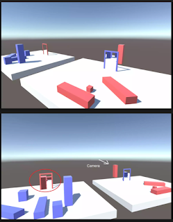
As you can see in the lower image, the red pillar behind the blue door shows up in the red door frame. We definitely do not want to see this as we should only see things in front of the blue door in the red door portal.
To fix this I did a bit of pondering (and Googling) and realised I needed to correctly update the portal camera projection matrix to ensure the near clip plane aligned with the plane of the portal. I’d experimented with doing this by adjusting the near clip, but the issue is the near clip plane is orthogonal/perpendicular to the camera view direction, not the normal of the portal, so you get unwanted clipping when looking at the portal at sharp angles. To adjust the near clip plane correctly one must use a technique called oblique projection - you can read more about it here and here.
I don’t want to go into all the excruciating detail, but in order to ensure the normal of the plane of each portal was correct (facing out of the portal), for the destination/corresponding transform, I have to rotate it by 180 degrees about local up (Y in this case) in the Portal.cs script so the portal cameras transform is the mirror of the source camera. Before, I had ensured the source/destination transforms in Unity were the mirror of one another (as you can see in an earlier screenshot), but this was no good as then I couldn’t use the forward vector of the transform (portal surface normal) for one of the portals to create the oblique projection matrix (essentially in the example above, one portal would look fine, and the other wouldn’t work at all!)
So now each portal (door) has its transform set so that local Z is pointing out of the surface. I use this to create a plane (the surface normal/forward vector of the portal, and the position in world space of the portal), transform it to camera space (multiply the plane by the inverse transpose of the camera transform) and then build an oblique projection matrix from this plane. This ensures the near clip plane is aligned to the portal surface. With that, everything now looks correct! We don’t see the red pillar rendered as it is now correctly clipped, and we don’t see any incorrect clipping when looking at the portal from sharp angles as the near clip plane is correctly aligned with the portal!
If you take a look at Portal.cs in the GitHub project you should be able to see all the individual steps!
I hope this has been some more help to anyone interested in this area!